Correctly Wire Your Wall Switch

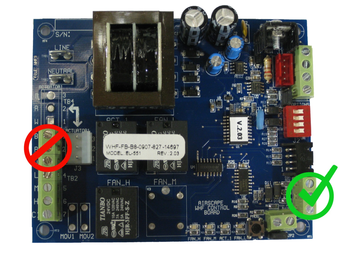
This is a brief reminder of the proper location for wiring the wall switch to your AirScape control board. We have noticed that sometimes people, even licensed electricians, wire the wall switch to the auxiliary actuator terminal (red crossed out circle). Wiring at this incorrect location will blow the 3 amp circuit breaker on your unit and possibly damage your control board. Regardless of your experience level we recommend looking at the wiring diagram in the instruction manual before wiring the wall switch. The correct wiring location is indicated by the green circle with check mark.

Related Posts: HOW TO WIRE THE WALL SWITCH

Unique and Challenging Installs – introduction

Did you find your install particularly challenging because of your attic configuration? Did you have a unique install that went beyond the traditional install method? Or are you just proud of your DIY project? If you answered yes to any of these questions we would love to see your installation photos. Hopefully, your unique or challenging install will help someone overcome an obstacle in their installation or just show them what’s possible beyond the norm. With that being said, we are starting an ongoing blog series on unique and/or challenging installs. This series is open to both home owners and installers.

So, if you feel that your installation could be helpful, please send your photos and answers to the questions below to: experts@airscapefans.com

What was the most challenging part of the installation?

On a scale of 1 to 5 how difficult would you rate this installation? (1 easy – 5 difficult)

What advice would you give to someone doing this installation?

How much of a “Do-it-yourselfer” are you? ( 1 what’s a hammer? – 5 fix everything myself)

Sound Reduction part 4 – Ducted Models

The final step on our journey of sound reduction brings us to ducted AirScape models. As you already know the ducted design of the 2.5 WHF, 2.5e WHF, 4.4e WHF, 4.5 WHF, and the Kohilo 2.8 allow for maximum airflow with a minimum of noise. Improper installation of these models can increase their sound levels. We touched on this subject earlier in the blog “4.5 Installation – Maximize Airflow, Minimize Noise.” There are a few things you need to consider when installing a ducted model.


90 DEGREE BEND –  The 90 degree bend should be as smooth as possible to maintain the 20″ diameter of the ductwork. Kinking the ductwork will increase the sound level and reduce airflow because the air does not have a smooth path to the fan.


EXTENSION –  It is important to extend the ductwork as far as possible away from the damper box. This needs to be done without distorting the 90 degree bend in the ductwork. Extending the ductwork fully moves the sound source (the fan) to the farthest point from the living space.


D-RINGS –  The 2.5, 2.5e, and 4.4e fans have D-rings which are used to hang the fan from the attic rafters. Only 4 of the 8 D-rings are used in the installation. The unused D-rings should be taped down to avoid excess rattling.


PART 1 / PART 2 / PART 3 / PART 4

Sound Reduction part 3 – Raised Frame w/ Ductboard

The next logical step for sound reduction is to combine the raised frame concept and add the duct board mentioned in part 1. In the following steps we’ll show you how to do this type of install.


STEP 1:  First we created two frames with inside dimensions of 14.5″x22.5″ using 2×4’s.


STEP 2:  Next we made a box using the two frames from step 1 and 3/8″ plywood. For this example we made our raised frame 17″ tall using (2) 25.5″ x 17″ and (2) 18.25″x17″ pieces of plywood. The vertical clearance of your attic will determine how tall of a box you can create. The picture shown is with one side removed.


STEP 3:  Position the box over the framed opening and secure. Caulk all of the seams and gaps of the newly constructed raised frame. Attach the provided gasket to the upper frame of the box. Line the box between the 2×4 frames with duct board. In this example we used (2) 24″x10.75″ and (2) 16″x10.75″ sections of duct board. We decided to go with a friction fit, but adhesive or screws with flat washers would work as well.


STEP 4:  Position the unit on top of the raised frame (1.7 shown). Secure using the provided screws. From the living space caulk all the gaps between the unit and the framing. You can now follow the remaining steps in the installation and operation manual to finish your install.


PART 1 / PART 2 / PART 3

Sound Reduction part 2 – Raised Frame

You may consider a raised frame for your 1.0 or 1.7 WHF for additional sound reduction. The raised frame increases the distance between the fan and living space. Like our ducted models, making the fan slightly more remote from the living space will decrease the overall sound level. The height of the frame will depend on the total vertical clearance of your attic. The construction is very simple and will add a few additional steps to your installation.


STEP 1: We made a raised frame using some scrap 2×4’s. The inside dimension is 14.5”x22.5” matching the framed opening. Secure the raised frame to the attic floor.


STEP 2:  Caulk all of the frame gaps and joints. Place the provided foam rubber gasket on top of the raised frame.


STEP 3: Secure the unit to the framing (1.7 WHF shown). From the living space caulk all gaps between the unit and the framing.


STEP 4: It’s not a bad idea to add some insulation around the raised frame. You can now follow the remaining steps in the installation and operation manual to finish your install.


PART 1 / PART 2