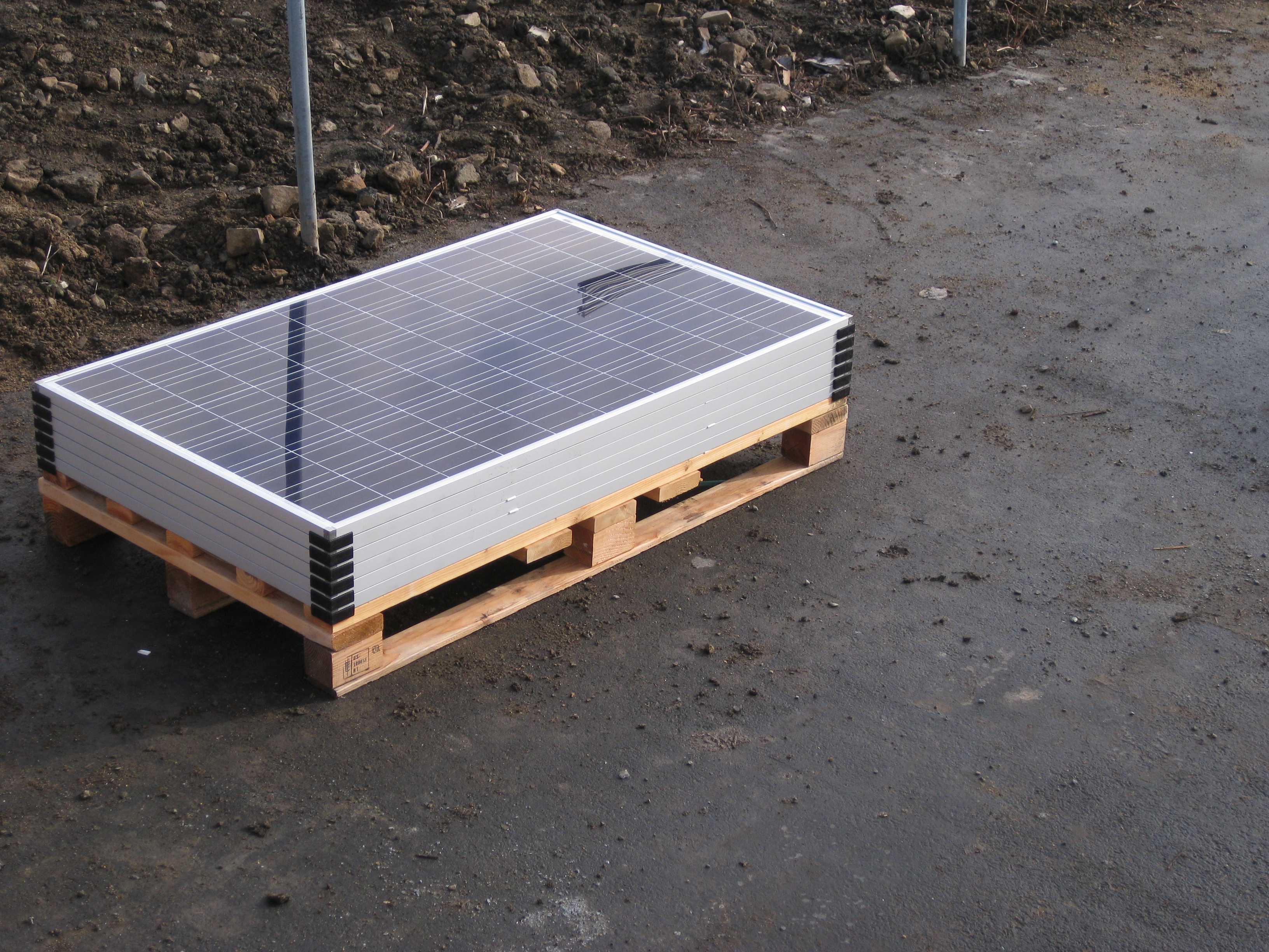
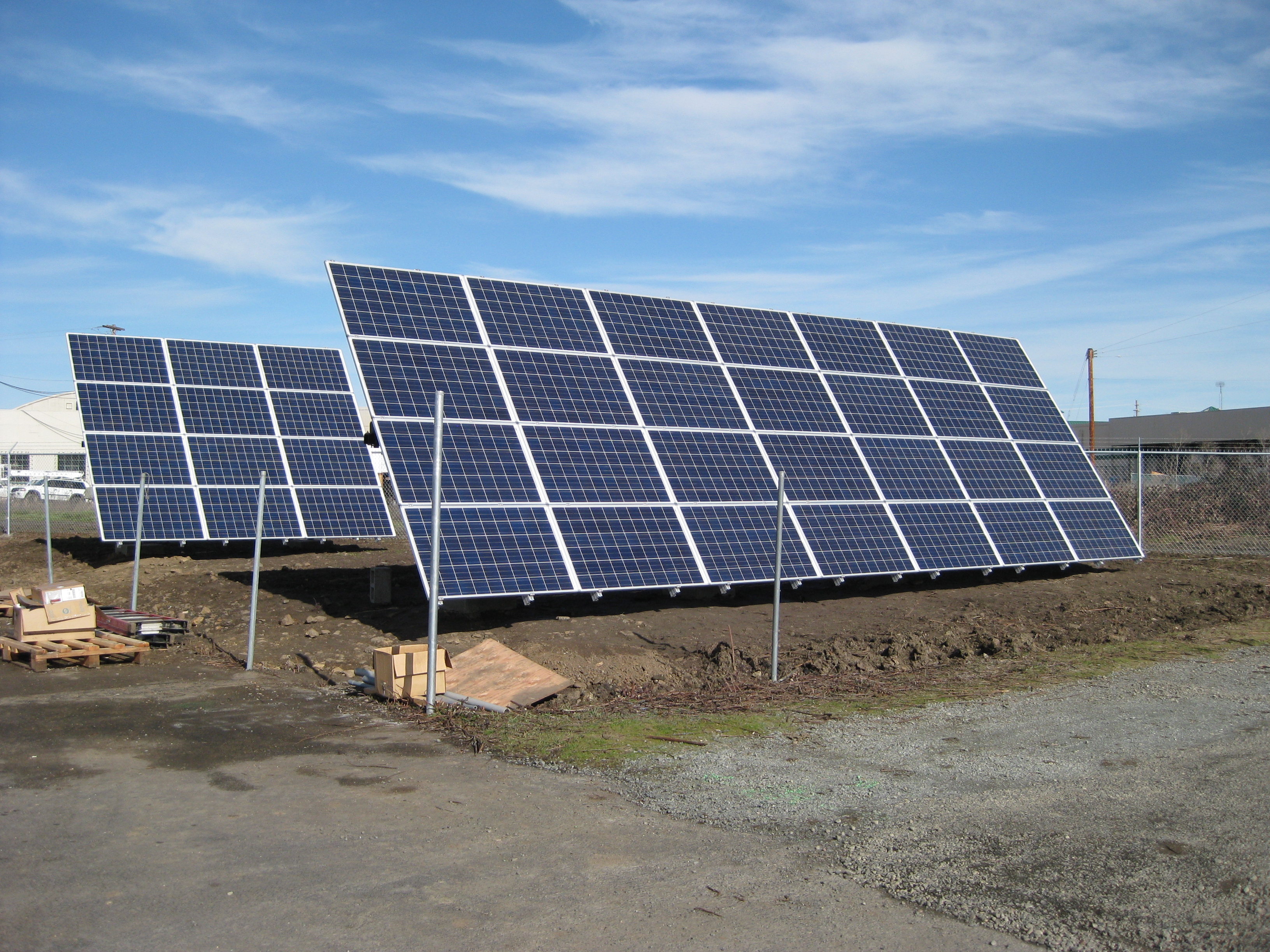
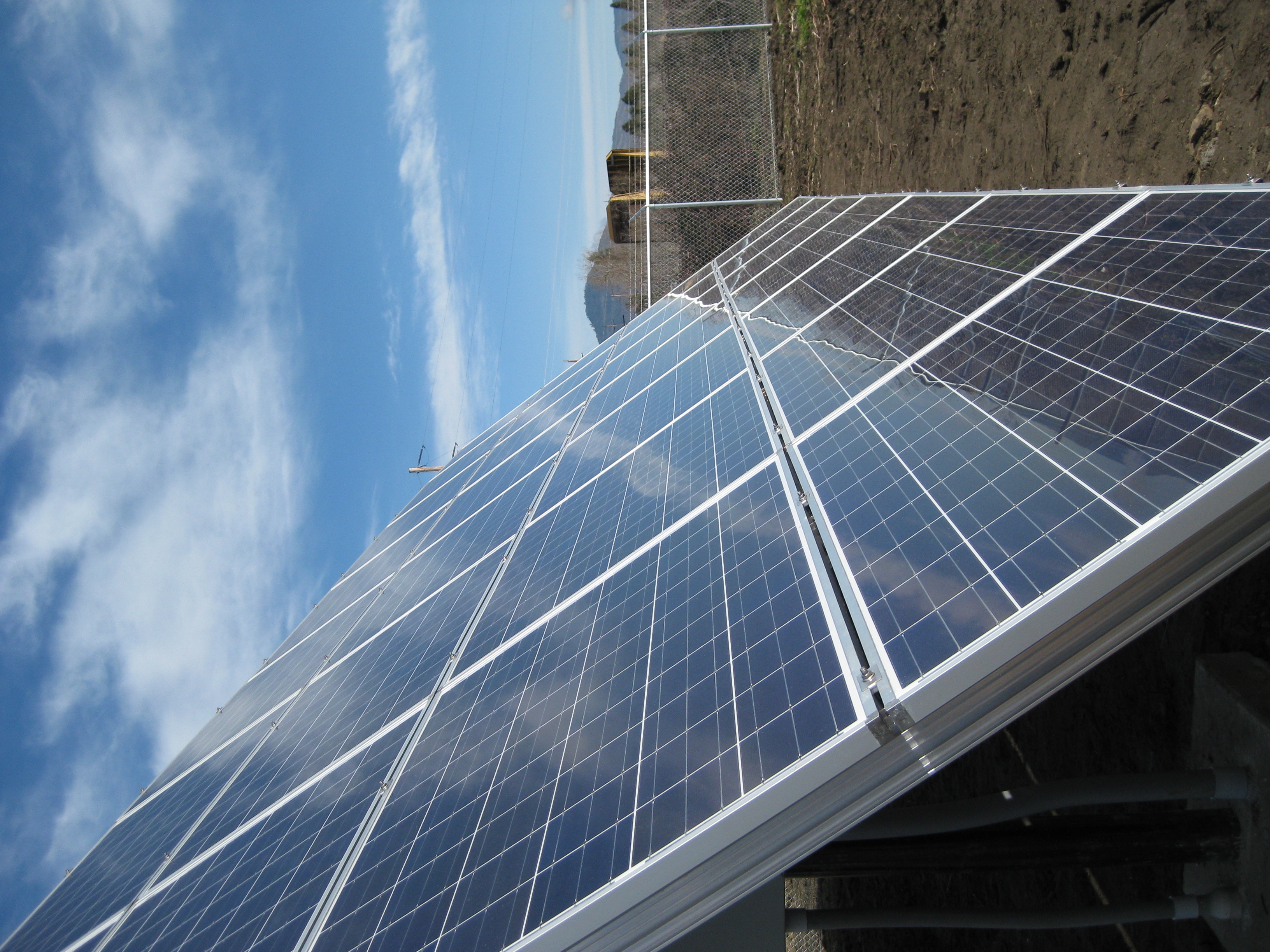
With the solar panels installed we are just waiting for a final electrical inspection from our local utility and we can begin producing energy.
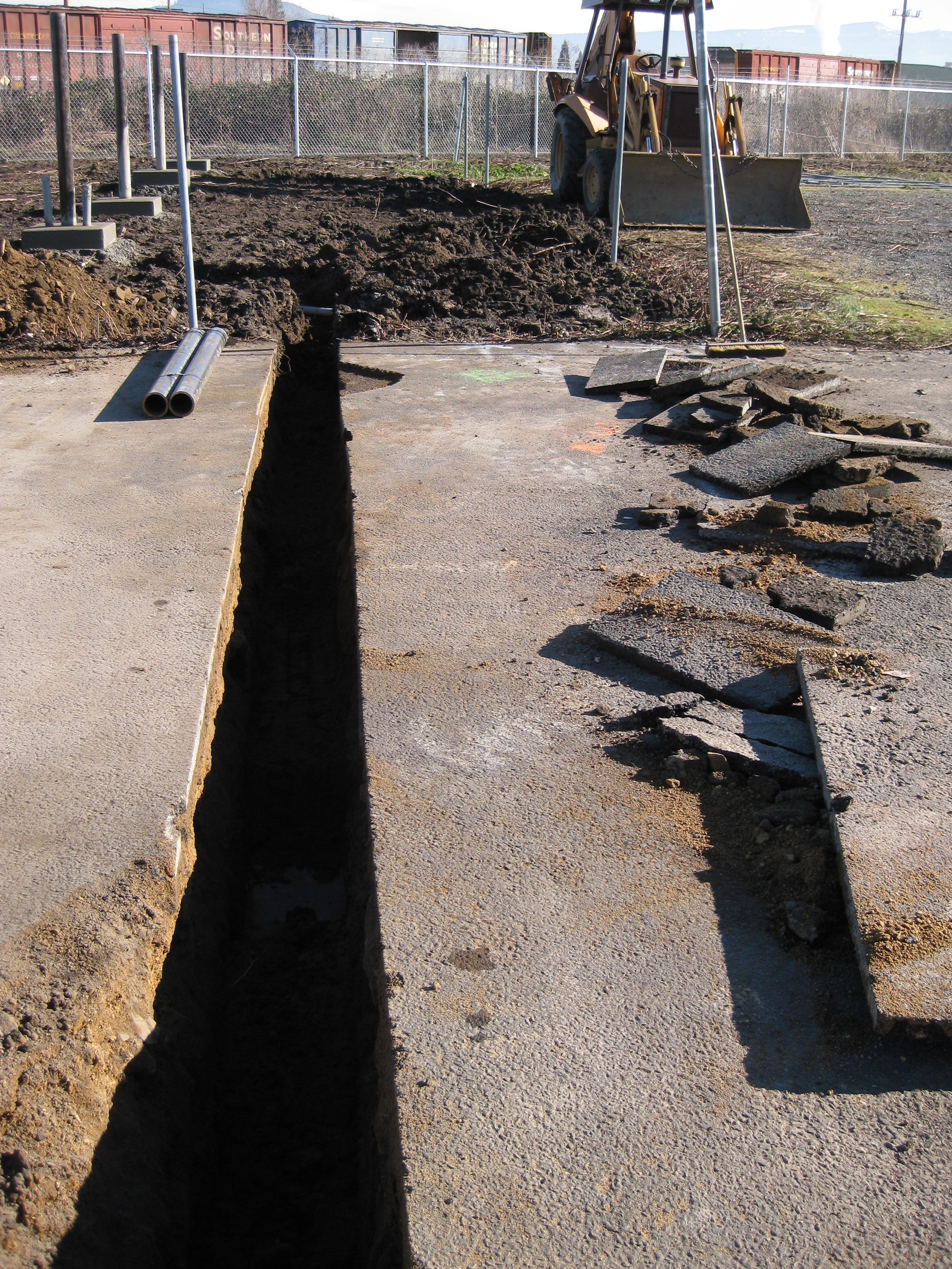
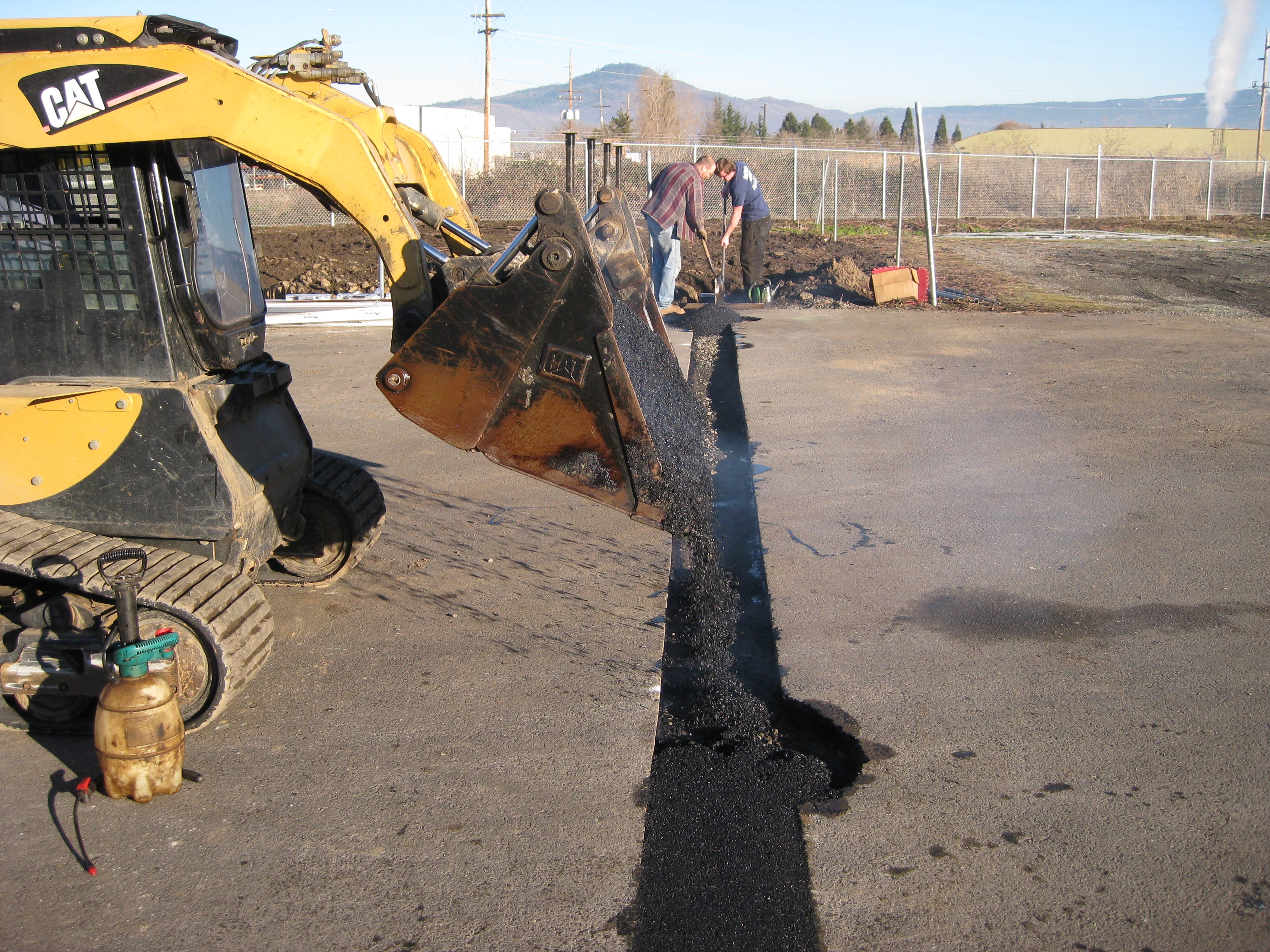
The third phase of our installation was to dig a trench from the solar site to our main facility. Conduit was then installed in the trench to run power cables from the solar panels to the building. The trench was then back-filled and on the next warm day was paved over with asphalt.

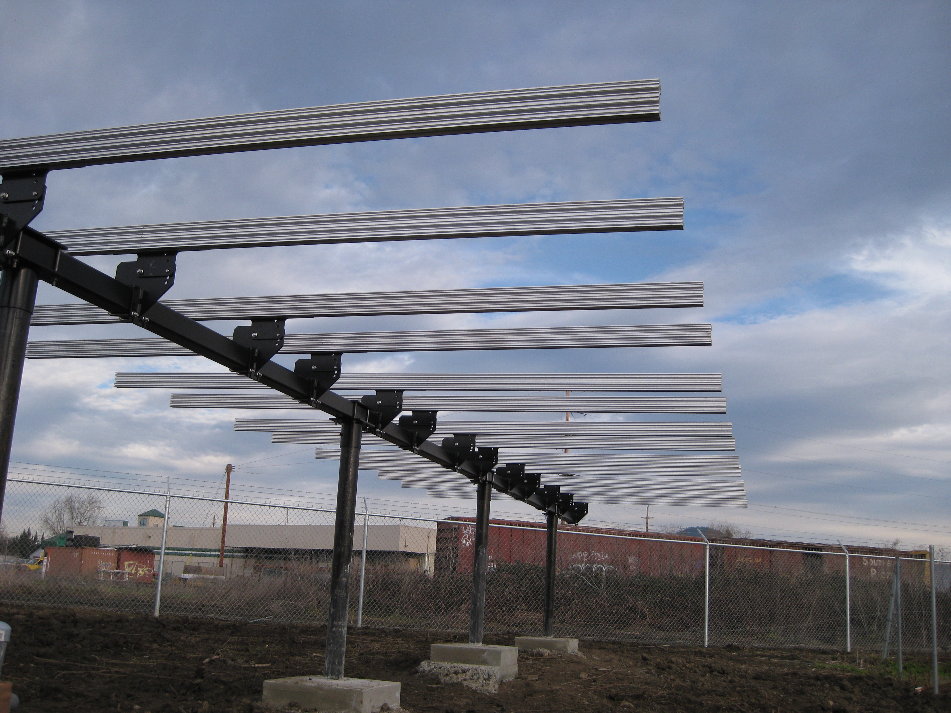
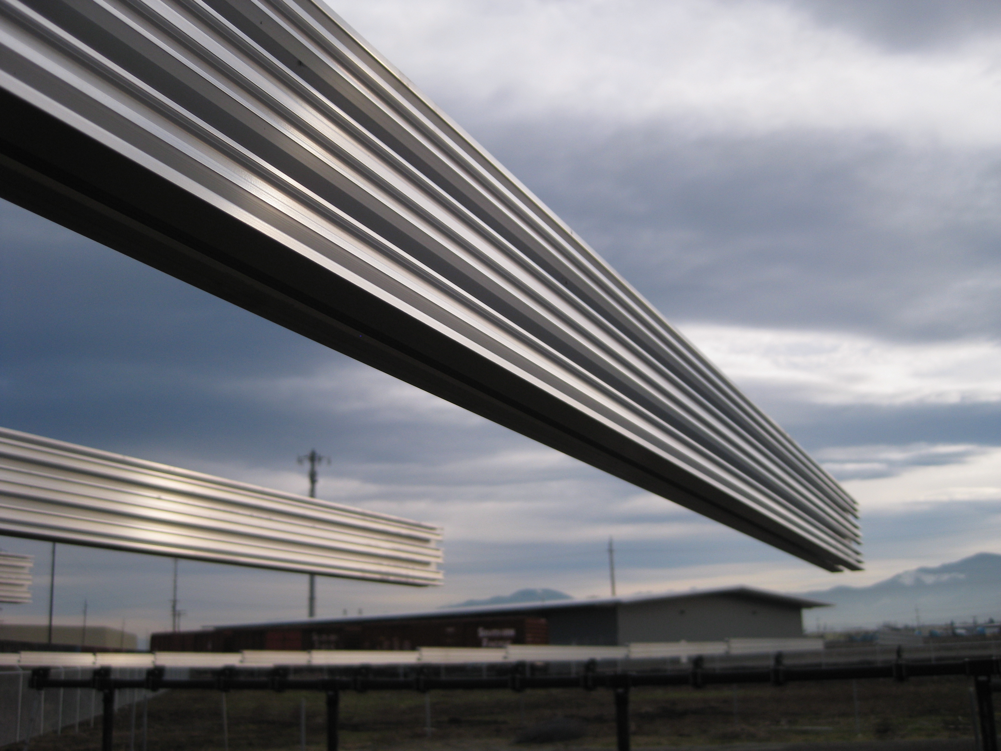
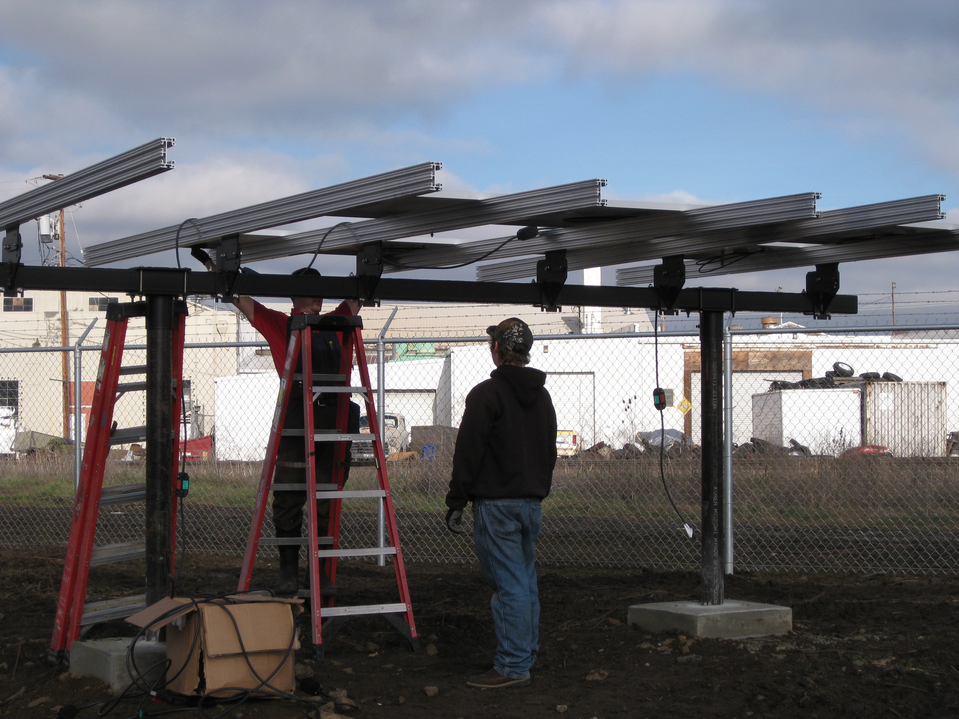
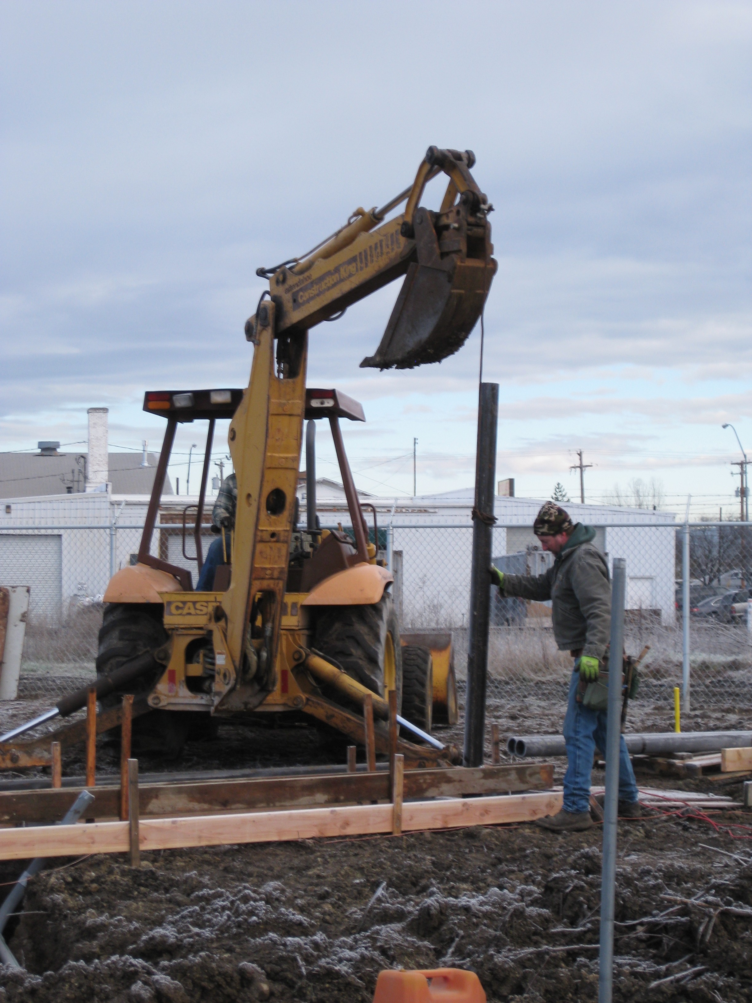
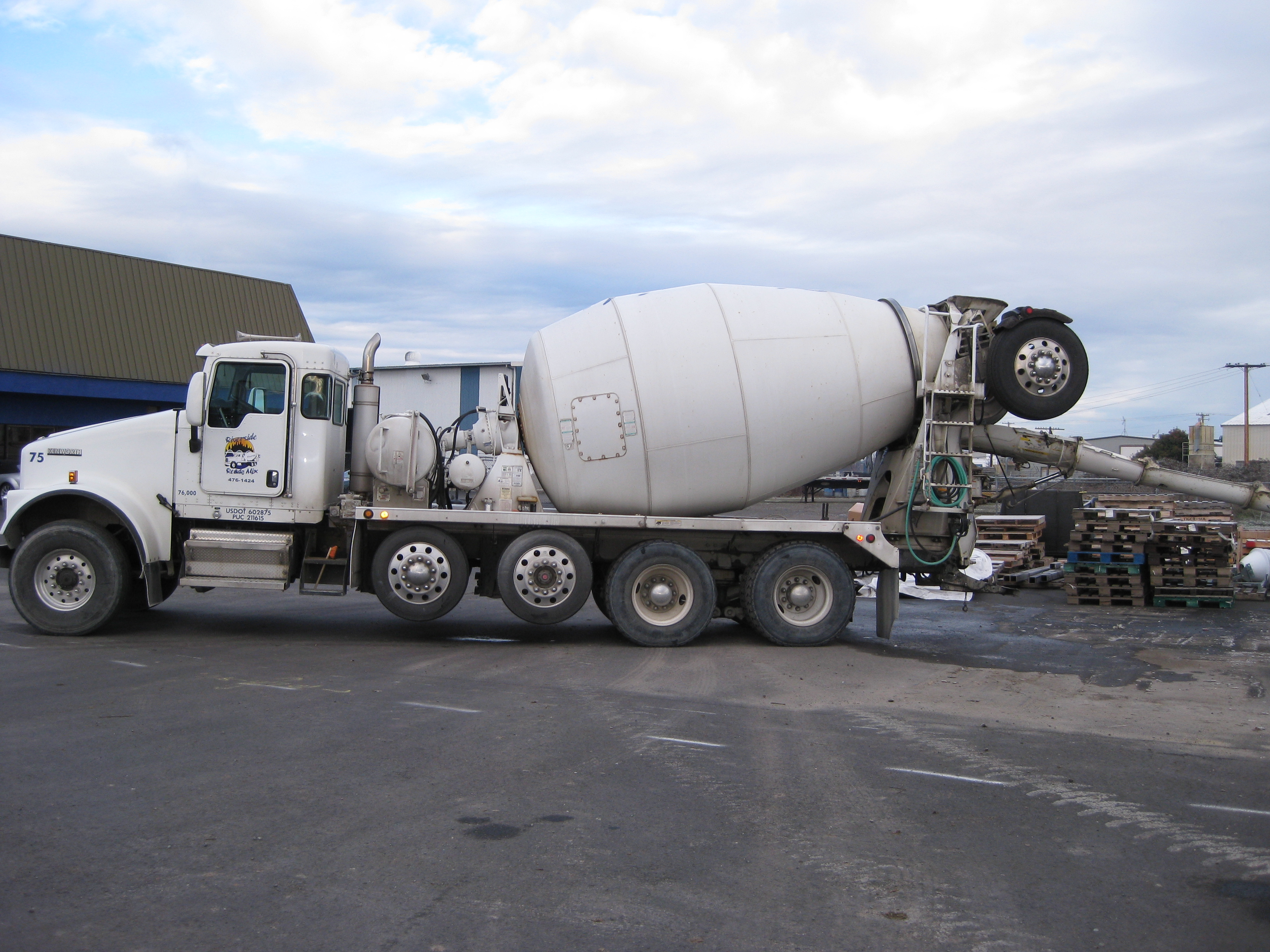
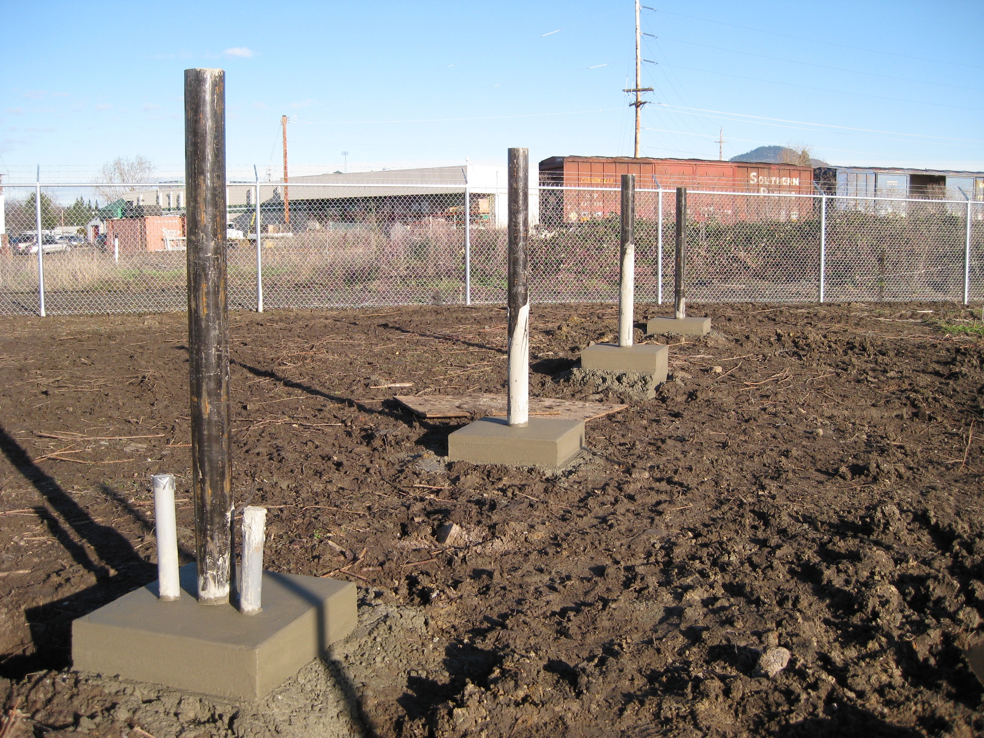
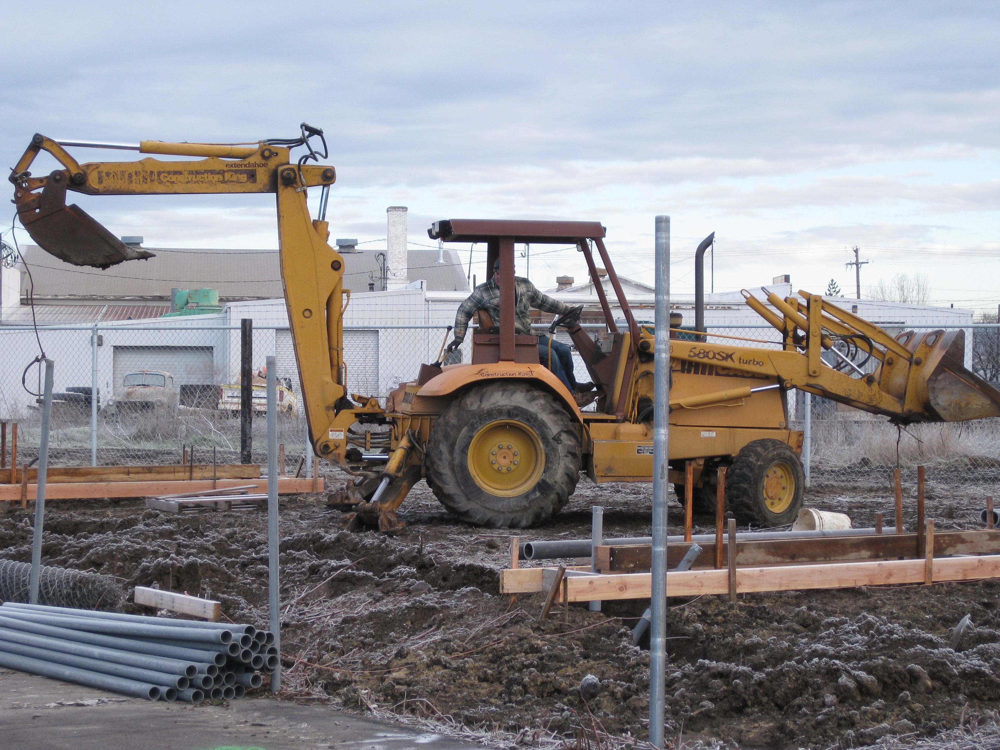
Our solar install continues weather permitting (a Southern Oregon winter is a rainy mess) Between rain showers we were able to complete the second phase of construction.
PART 1 / PART 2 /
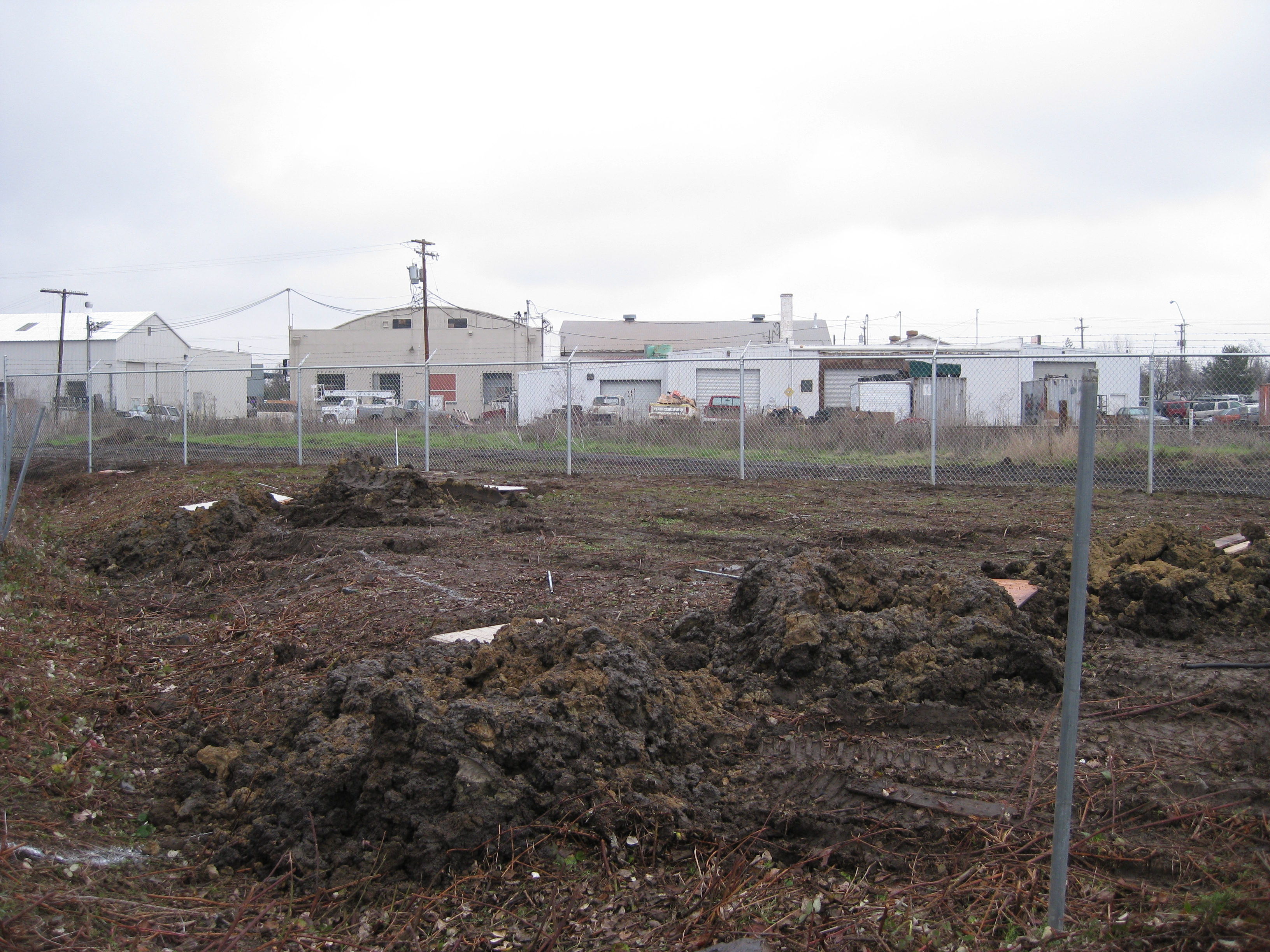
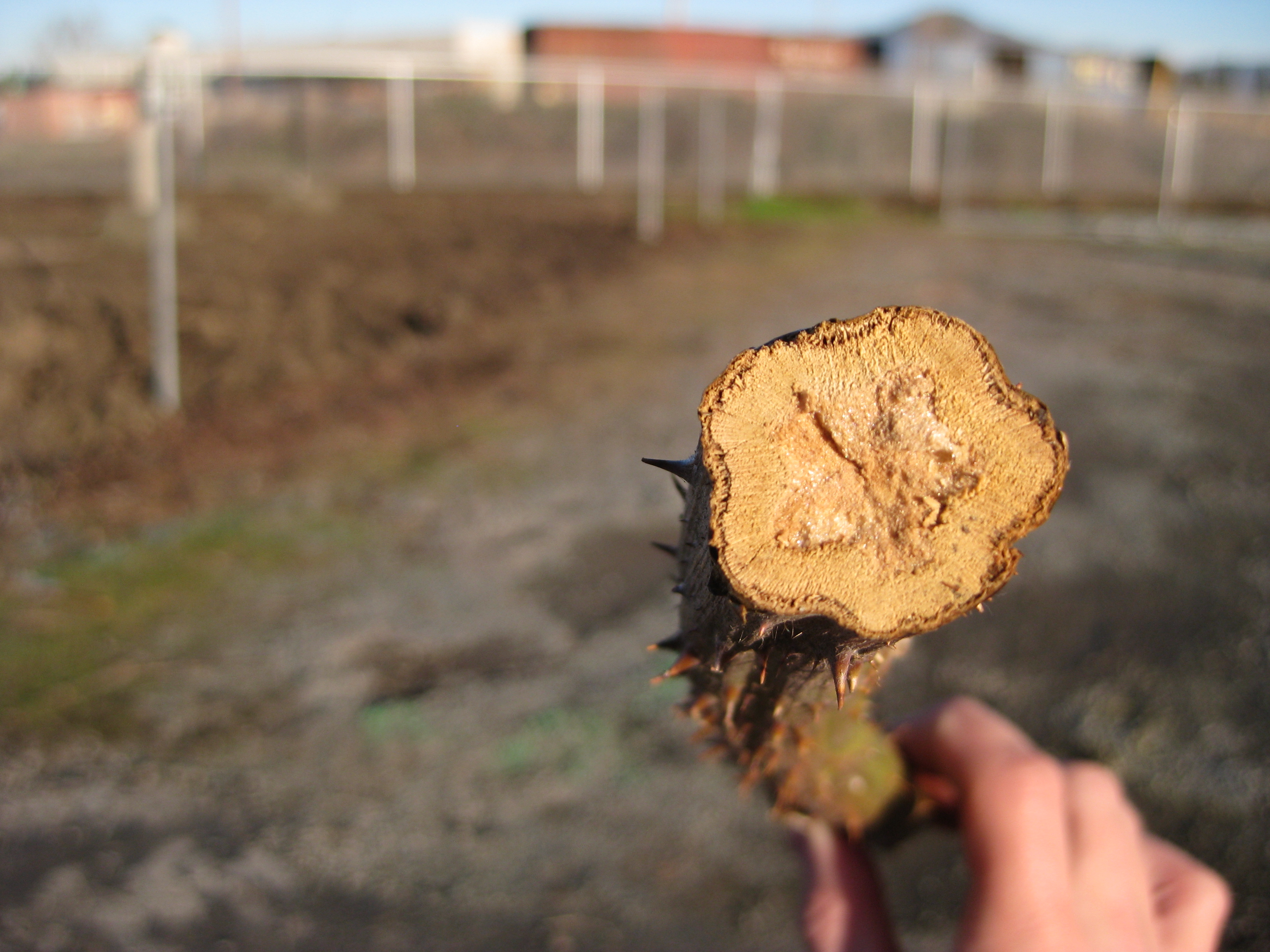
We thought we would share some pictures of our new solar installation here at AirScape HQ. We chose a site on an unused corner of the property that is perfectly situated for our solar install . The site was cleared of a massive blackberry bush so that work could begin. Blackberries are an invasive species here in Oregon so we didn’t feel too bad about removing them even though they were so delicious. We’ll put up more pictures as the work continues.
PART 1 / PART 2 /
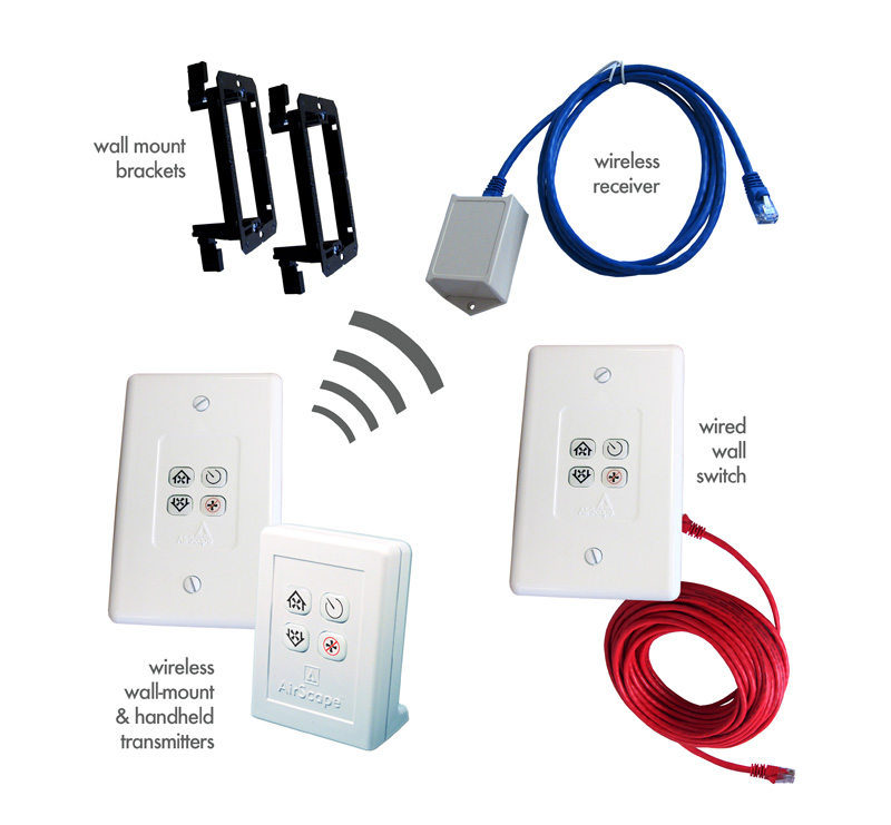
The next generation of whole house fan controls have shipped.
Some of the features:
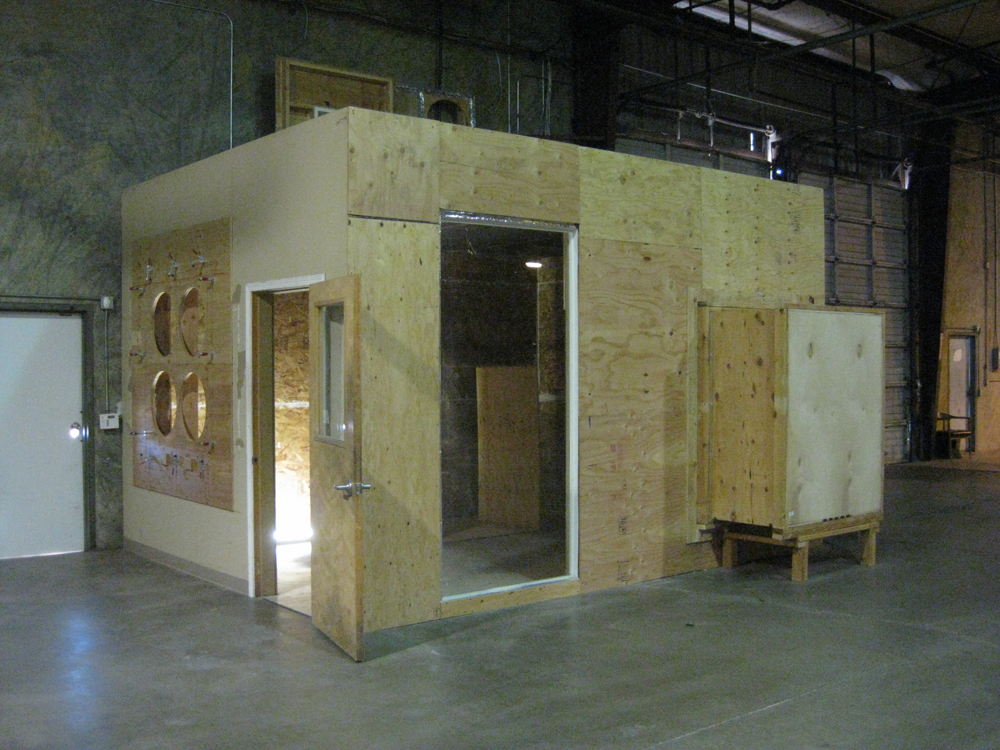
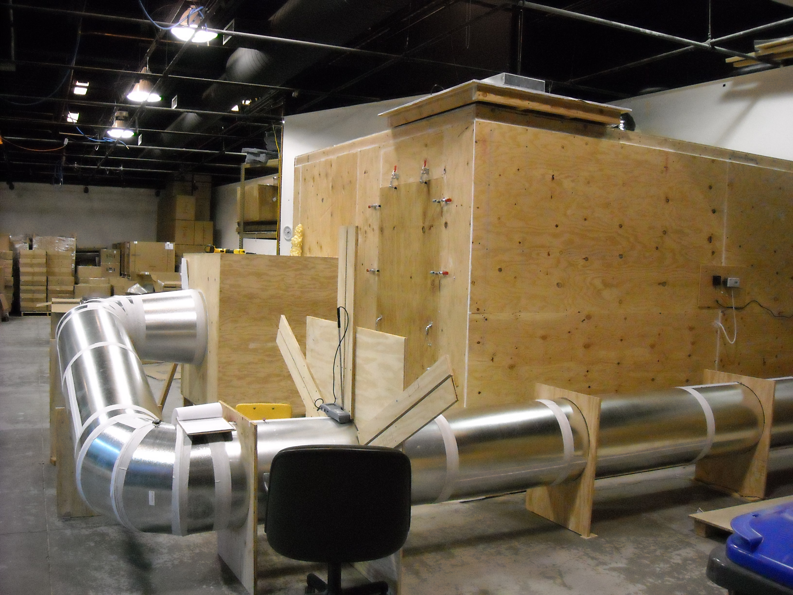
A little while ago we began to revamp and rebuild our fan test lab to make it bigger, better, and easier to use. We thought it would be fun to share some of the pictures of the construction of this new test facility.
A little background: We test all of our units to ensure that when we say it is 1710 CFM and 157 watts, that it is actually 1710 CFM and 157 watts. All of our Whole House Fans (WHF) are tested as you would install them in your home. Often the other guys will just test the fan itself and “forget” to test their WHF as a system (damper box, fan, duct, and grille). This kind of testing leads to misleading results, specifically greater CFM and lower watts than when installed as a system.
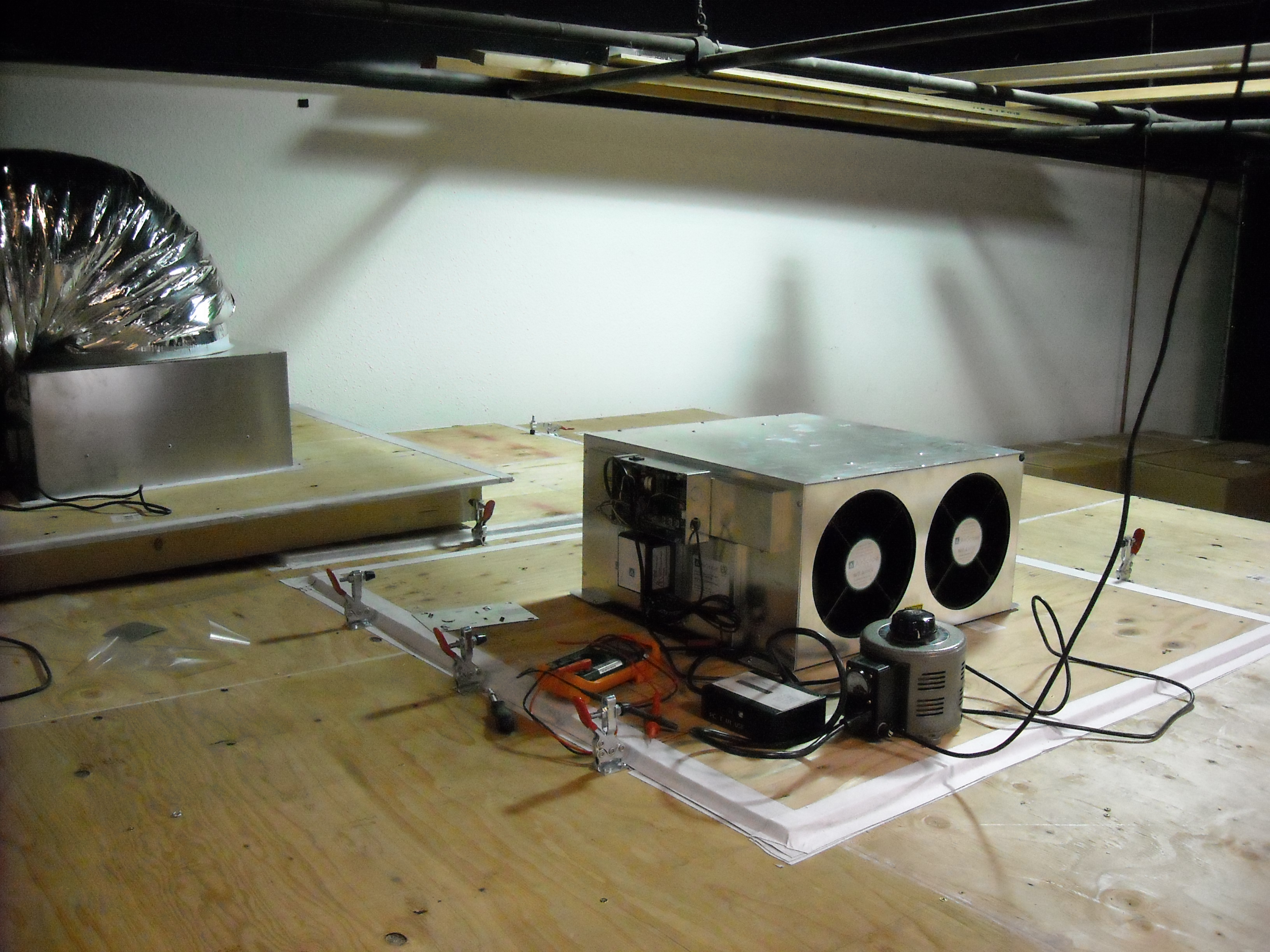
The old: This facility used a traverse method of testing airflow. We used a calibrated and certified hot wire anemometer to test air velocity. Soon after this picture was taken we straightened the silver tube, as we found the two bends were causing pressure waves affecting the testing.

Testing: A 1.7 WHF about to be tested as installed in the attic. We used a multimeter and a power meter, both calibrated and certified, to measure volts and watts.
The new: The new and improved test lab under construction at our warehouse in Medford, OR. Check back soon for more pictures of the construction process.