Installation for attics with loose fill insulation

Loose Fill Insulation

We often get asked if AirScape whole house fans can be installed in attics with loose fill insulation. The answer is yes, with one additional install step. The idea is to stop the insulation from being displaced by the air movement generated by the AirScape. We now offer a breathable synthetic fabric that can be placed on top of the insulation to stop any displacement. The installation is as simple as laying the material down in the attic where the fan discharges and tacking or weighting it down. The final step would be to turn the AirScape on and adjust the fabric material as needed.

The Loose Fill Insulation Cover (LFIC) is available in 9’x10′ sheets and can be found on any of the product pages on the website.

4.4e/4.5 Install: Low Attic Clearance

Often a WHF will not easily install in the traditional horizontal position. In some instances trusses or other obstructions will interfere with a normal installation. More often there is not enough clearance between the attic floor and the roof. One solution is to create a plenum box which the WHF will attach to. The plenum box can easily be constructed out of plywood and 2×4’s.  The red line in the photos represents the plenum box constructed for an AirScape 4.4e installation. The flexible ductwork and fan can then be mounted straight off of the damper box (the ductwork may have to angle slightly upward so that the fan does not touch the attic floor). A 90 degree bend in the ductwork is not necessary for sound attenuation in this application.

Installation Notes:

– Line the inside of the box with a layer of sheetrock to maintain any required fire ratings

– Use a sound attenuating duct liner for maximum sound reduction

– Seal all framing joints with latex caulk to make the box air tight

– Insulate the outside of the box to minimize heat loss

– Support any sags in the ductwork with additional chain

Where to find your AirScape model, version, and serial number

If you decide to add a remote kit after your initial purchase, the AirScape model, version, and serial number will be required in order to give you the correct remote for your unit. This information is also needed by our technical support staff to diagnose or troubleshoot an issue with your WHF.

4.5 Installation – Maximize Airflow, Minimize Noise

Recently we have been using our new and improved sound testing chamber to make sound comparison videos of our different models. The shooting of these videos reminded us that the set up of the ducted models will make a significant difference in the CFM and noise levels. Basically, improper installation will decrease the unit CFM and increase the amount of noise. Some numbers for comparison:

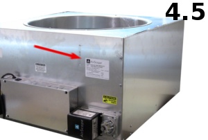
AirScape 4.5 improper installation –  high 59 dBA / low 50 dBA

AirScape 4.5 proper installation –  high 55 dBA /low 46 dBA ……A 4 dBA difference!

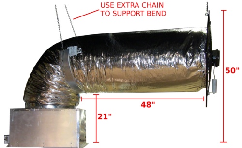
The photo above shows the correct install dimensions for the 4.5 WHF. You will notice that we have a nice even bend and the ductwork is fully extended (Note that we used an extra length of the provided chain to help support the bend). It is important to maintain the 20″ diameter of the duct through the 90 degree bend. This will ensure that you get unrestricted airflow through the duct and will help disrupt the sound waves. You also want to make sure the duct and fan are fully extended from the 90 degree bend. This moves the fan to the furthest point from the grill opening, thus decreasing the decibel level.

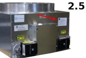
Airscape 2.5/2.5e installation: The install dimensions for the AirScape 2.5/2.5e are very similar. The duct should be 21″ from the attic floor. It should extend 44″ from the 90 degree bend to the fan (you may be able to extend it to 48″ if the bend is supported as shown in the photo above). The top of the fan should be 44″ from the attic floor.

Interlock / Master Override

interlock3The newest version of our control board has a master override or interlock. The interlock, which is now required by some building codes, effectively disables the WHF by closing the damper doors and turning off the fans. It is often used in conjunction with smoke detectors or mechanical systems located in the attic. The idea is that if the furnace turns on or the smoke detector goes off the WHF will shut down. This could slow down the spread of a fire or save $$$ if the furnace was accidentally turned on.


The interlock is integrated into our 24v digital controls on V4 of our control board. To use the interlock simply remove the two-pin shunt and run low voltage wire from the interlock screw terminals to the relay on the device that will disable the WHF. To activate the interlock the relay should interrupt the 24v current. Do not wire 120v to the interlock.


When activated a solid red LED will illuminate on the WHF control board. The fans will turn off and the damper doors will close. Once the interlock is disengaged, the LED will go out. The WHF can be restarted by flipping the wall switch off and on again or by using your remote.


interlock1

interlock2

Control Board Identification

When you call in with a tech support issue we will want to know which version of our control board is controlling your unit. This is important because it will help us properly diagnose what is going on with your WHF. In most cases we can determine the control board version if you give us the model information for your AirScape. The model is listed on a sticker found on the unit (near the junction box on the 1.7, 2.5, 4.5 and on the damper door of the 1.0). Occasionally the model sticker isn’t enough. If you are already going into the attic to write down the model information you might as well take a look at the control board as well.

The control board has had several different incarnations over the years. Please take a look at the photos below and identify your control board before you call tech support.

My control board looks most like: 1, 2, 3, 4, 5 or 6 (Differences between 3 and 4 circled in red)

1C1_blue_300x250 2C1_green_300x250

3B8_10_300x250 4B7_300x250

5B5_6_300x2506