Over the years ve’ve also fielded a lot of questions from customers wanting to know if our fans’ dampers can be installed vertically (i.e. in a wall rather than over a ceiling) or at an angle on top of a vaulted ceiling. The short answer to both questions is “yes”, but there are some important limits that need to be considered, which we’d like to go over. Please note: this blog post is limited to our line of AirScape fans—Kohilo models will be covered in a future post.
2.5e WHF
Unique and Challenging Installs – #1

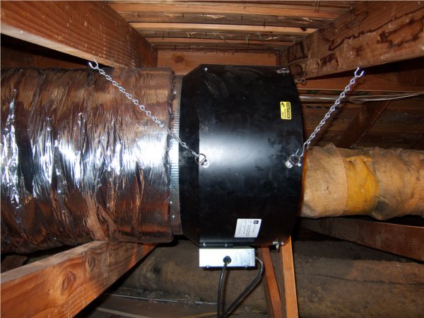
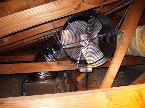
The first challenging install in our series comes from Anker in California. We love this challenging install because of the way he overcame the low attic clearance and the collar beams you can see in the photos (Click photos to enlarge).
Anker’s challenge was to find a suitable damper box location that was free of electrical junction boxes but also did not have a collar beam above it. The next challenge was to find a location for the fan where the ductwork could be installed properly (90 degree bend and fully extended). In this attic the path of the duct and fan would have run into a collar beam. To overcome this Anker made a scale drawing of the attic and also laid out the ductwork on the ground to mock up the installation. His next step was to mount the damper box and then hang the fan. By hanging the fan before attaching the ductwork he was able to determine where it would fit best. The final step was to attach the ductwork to the damper box, feed it over a collar beam and attach it to the fan.
The advice Anker would give anyone doing this installation would be to:
Use a helper when hanging the fan (due to the weight)
Have an electrician wire the outlet
Pre-drill holes for attaching the duct to the fan collar
RELATED POSTS: Unique and Challenging Installs – introduction
Sound Reduction part 4 – Ducted Models
The final step on our journey of sound reduction brings us to ducted AirScape models. As you already know the ducted design of the 2.5 WHF, 2.5e WHF, 4.4e WHF, 4.5 WHF, and the Kohilo 2.8 allow for maximum airflow with a minimum of noise. Improper installation of these models can increase their sound levels. We touched on this subject earlier in the blog “4.5 Installation – Maximize Airflow, Minimize Noise.” There are a few things you need to consider when installing a ducted model.
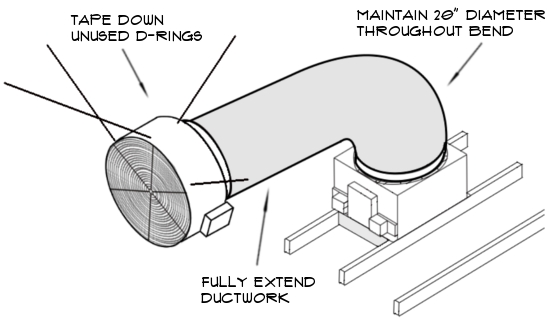
90 DEGREE BEND – The 90 degree bend should be as smooth as possible to maintain the 20″ diameter of the ductwork. Kinking the ductwork will increase the sound level and reduce airflow because the air does not have a smooth path to the fan.
EXTENSION – It is important to extend the ductwork as far as possible away from the damper box. This needs to be done without distorting the 90 degree bend in the ductwork. Extending the ductwork fully moves the sound source (the fan) to the farthest point from the living space.
D-RINGS – The 2.5, 2.5e, and 4.4e fans have D-rings which are used to hang the fan from the attic rafters. Only 4 of the 8 D-rings are used in the installation. The unused D-rings should be taped down to avoid excess rattling.
PART 1 / PART 2 / PART 3 / PART 4
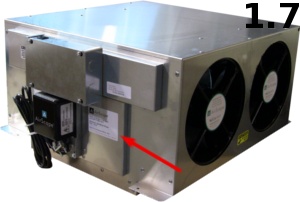
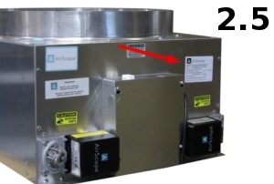
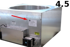
Where to find your AirScape model, version, and serial number
If you decide to add a remote kit after your initial purchase, the AirScape model, version, and serial number will be required in order to give you the correct remote for your unit. This information is also needed by our technical support staff to diagnose or troubleshoot an issue with your WHF.

4.5 Installation – Maximize Airflow, Minimize Noise
 Recently we have been using our new and improved sound testing chamber to make sound comparison videos of our different models. The shooting of these videos reminded us that the set up of the ducted models will make a significant difference in the CFM and noise levels. Basically, improper installation will decrease the unit CFM and increase the amount of noise. Some numbers for comparison:
AirScape 4.5 improper installation – high 59 dBA / low 50 dBA
AirScape 4.5 proper installation – high 55 dBA /low 46 dBA ……A 4 dBA difference!
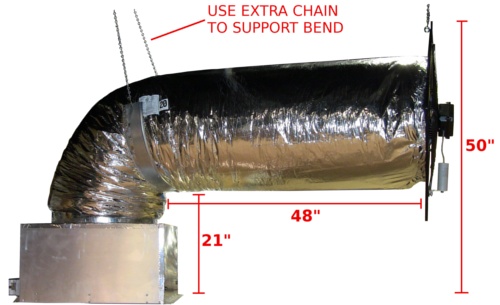
The photo above shows the correct install dimensions for the 4.5 WHF. You will notice that we have a nice even bend and the ductwork is fully extended (Note that we used an extra length of the provided chain to help support the bend). It is important to maintain the 20″ diameter of the duct through the 90 degree bend. This will ensure that you get unrestricted airflow through the duct and will help disrupt the sound waves. You also want to make sure the duct and fan are fully extended from the 90 degree bend. This moves the fan to the furthest point from the grill opening, thus decreasing the decibel level.
Airscape 2.5/2.5e installation: The install dimensions for the AirScape 2.5/2.5e are very similar. The duct should be 21″ from the attic floor. It should extend 44″ from the 90 degree bend to the fan (you may be able to extend it to 48″ if the bend is supported as shown in the photo above). The top of the fan should be 44″ from the attic floor.
Changing Fan Speed Settings on Your AirScape 2.5e
 Not only does the AirScape 2.5e have phenomenally low energy use, the user can also select up to 5 different CFM settings. The 2.5e fan motor has inputs which we program at different CFM. From the factory it is set for a low speed of 1512 CFM at 42 watts and a high speed of 2536 CFM at 196 watts. Now let’s say that the factory low speed setting does not provide enough airflow to properly cool your home over night. The fan speed settings can easily be adjusted for more airflow. For example, you could change the low speed from 1512 CFM to 2080 CFM. At the same time you could also adjust the high speed setting so that the fan will move 2604 CFM on high (see example #2). This is as simple as moving the low and high speed wires on the 2.5e fan control board (located on the fan housing) to different connections. The fan speed adjustment is described below:
- Turn your 2.5 e off. Unplug the fan power cord and turn off power to the damper box by unplugging it or switching the circuit breaker off if hardwired.
- Remove the fan junction box cover (located on the fan housing).
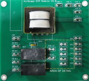
- Move the low and high speed wires to different taps to adjust fan speed (see photos).
- Plug in the fan power cord and turn the damper box power back on.
- The unit is now ready to operate at the new CFM settings.
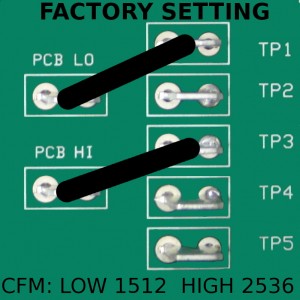
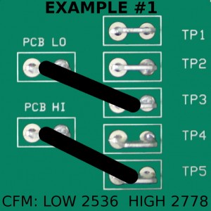
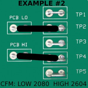
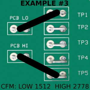
| TAP | CFM | WATTS |
|---|---|---|
| TP1 | 1512 | 43 |
| TP2 | 2080 | 108 |
| TP3 | 2536 | 197 |
| TP4 | 2604 | 216 |
| TP5 | 2778 | 258 |