Gen 2 Controls API

UPDATE: The controls referenced below are currently only available as an upgrade on Sierra units. For more information please call us at 866.448.4187.

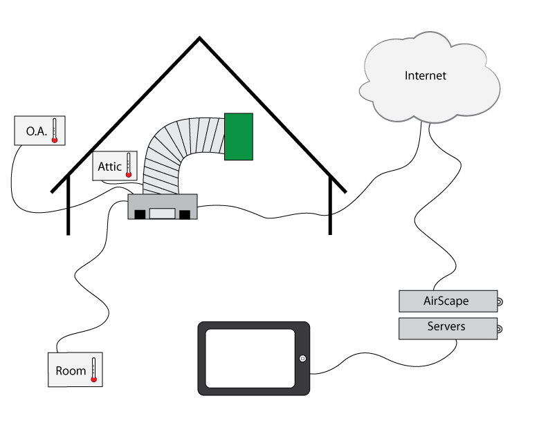
We have recently seen some very cool and imaginative integrations of the AirScape 2nd Gen Controls into home and building automation systems.  Frankly, we could not be happier as this was the intent of introducing network enabled fans like ours.  To help with future integration ideas, here is more info on how our controls communicate.

The API (application programming interface) for our whole house fan web server is very simple.  Its essentially an HTTP command sent to the controller.

http://controllerURL/fanspd.cgi?dir=|1|2|3|4|
where 1=fan speed up, 2=timer hour add, 3=fan speed down, 4=fan off

For example, if you want to turn OFF a fan at IP 192.168.0.20 the command would be:

http://192.168.0.20/fanspd.cgi?dir=4

When you send an API command, you also get an xml data stream back from the controller.

————–Example of xml data ——————

fanspd<fanspd>0</fanspd>
doorinprocess<doorinprocess>0</doorinprocess>
timeremaining<timeremaining>0</timeremaining>
macaddr<macaddr>60:CB:FB:99:99:0A</macaddr>
ipaddr<ipaddr>192.168.0.20</ipaddr>
model<model>2.5eWHF</model>
softver: <softver>2.14.1</softver>
interlock1:<interlock1>0</interlock1>
interlock2: <interlock2>0</interlock2>
cfm: <cfm>0</cfm>
power: <power>0</power>
inside:<house_temp>72</house_temp>
<DNS1>192.168.0.1</DNS1>
attic: <attic_temp>92</attic_temp>
OA: <oa_temp>81</oa_temp>
server response: <server_response>Posted
OK<br/></server_response>
DIP Switches: <DIPS>00000</DIPS>
Remote Switch:<switch2>1111</switch2>
Setpoint:<Setpoint>0</Setpoint>

——————————————————–

If you want to get data from the controller without any control actions, you can send the same HTTP command string without the “?dir=|1|2|3|4|” suffix.

For example, if your fan is at IP 192.168.0.20 the command would be:

http://192.168.0.20/fanspd.cgi

For XML and JSON formatted responses use the following commands with your fan IP inserted:

http://192.168.0.20/status.xml.cgi  gives data in xml format
http://192.168.0.20/status.json.cgi  gives data in json format

As always, if you have any questions on the API or want to brainstorm about your integration call us at 866.448.4187 or email experts@airscapefans.com

Whole House Fan Monitoring

monitoring-line-drawing

What ? The  data monitoring package “DMP” is a new feature available for AirScape whole house fans. This package of extra sensors and software allows whole house fan owners to view room, outside, and attic temperatures. Users can view the temperatures through their browser enabled devices (smart phones, computers, tablets …). Historical data will be saved on AirScape servers and will only be available by secure login.

Why is this cool ? You will be able to check temperatures in your house, attic, and outside remotely. By looking at the graphs of temperatures, you’ll be able to decide on the best ways to save utility costs. Upcoming software will be able to total your annual energy savings.

When? Available in the next 2 weeks on select models.

Cost ?  The additional cost for the 3 temperature sensors (accurate to 1 deg F) and additional embedded software will be $49. Monitoring and web access: FREE

Privacy ? Your data  will only be available to you, secured by encrypted passwords. Aggregated data that does not reveal the user’s identity may be used for research purposes.

Want to see more about how it works? Check out the DMP DEMO PAGE

monitoring-package

How to Install and Program an AirScape LCF Remote Control

***** NOTE: THIS POST ONLY APPLIES TO THE LCF VERSION OF THE REMOTE CONTROL ******

1. Plug the remote antenna into the control board 4-pin connection

2. Program the remote transmitter by cycling the power to the WHF off and on (unplugging and plugging in the power cord) or by pressing remote reset button

– A red LED on the control board will begin to flash indicating that the control board is ready to mate with your remote transmitter

– Press any button on the hand held transmitter

– The red LED will blink off

– Your WHF is now ready to use

3. Repeat this process to program additional remote transmitters

How to Wire the Wall Switch

NOTE: This post does not apply to the Kohilo 2.8

All AirScape models, except the Kohilo 2.8, use low voltage controls (24 volt) to turn the unit on/off and switch between high and low speed. Never wire line voltage to your wall switch.

Run 18-22 gauge wire (x3) from the WHF to the wall switch location. Attach the 3 wires to the control board at the screw terminals COM RED, START BLK, and HI SPD BLU/WHT.

Connect the 3 wires to the wall switch (see below). We have pre-wired wire leads to the wall switch to indicate the wire locations. The wire leads correspond to the control board as follows: RED to COM RED, BLACK to START BLK, and WHITE to HI SPD BLU/WHT.

Related Posts: CORRECTLY WIRE YOUR WALL SWITCH


Correctly Wire Your Wall Switch

This is a brief reminder of the proper location for wiring the wall switch to your AirScape control board. We have noticed that sometimes people, even licensed electricians, wire the wall switch to the auxiliary actuator terminal (red crossed out circle). Wiring at this incorrect location will blow the 3 amp circuit breaker on your unit and possibly damage your control board. Regardless of your experience level we recommend looking at the wiring diagram in the instruction manual before wiring the wall switch. The correct wiring location is indicated by the green circle with check mark.

Related Posts: HOW TO WIRE THE WALL SWITCH

Interlock / Master Override

interlock3The newest version of our control board has a master override or interlock. The interlock, which is now required by some building codes, effectively disables the WHF by closing the damper doors and turning off the fans. It is often used in conjunction with smoke detectors or mechanical systems located in the attic. The idea is that if the furnace turns on or the smoke detector goes off the WHF will shut down. This could slow down the spread of a fire or save $$$ if the furnace was accidentally turned on.


The interlock is integrated into our 24v digital controls on V4 of our control board. To use the interlock simply remove the two-pin shunt and run low voltage wire from the interlock screw terminals to the relay on the device that will disable the WHF. To activate the interlock the relay should interrupt the 24v current. Do not wire 120v to the interlock.


When activated a solid red LED will illuminate on the WHF control board. The fans will turn off and the damper doors will close. Once the interlock is disengaged, the LED will go out. The WHF can be restarted by flipping the wall switch off and on again or by using your remote.


interlock1

interlock2