
We get a lot of questions about the ‘R value’ of our damper doors, so we felt that it’s worth going over the basics.
The so called ‘R value’ is denominated in the units of (square-feet x degree x hour/ BTU). Sounds complicated, but all you really need to know is:
Heat Flow Q (in BTU per hour) = Area x (temperature differential) / R-value
[For you techies, this formula is valid for steady state, and assumes an infinite plane area.]
Let’s do the math for our whole house fan dampers. We’ll assume VERY cold conditions in the attic (0° F) and 70° F inside.
| Model | length | width | Area (sq. feet) | R value | Q (BTUH) |
| 1.0WHF | 22.5 | 14.5 | 2.27 | 14 | 11.33 |
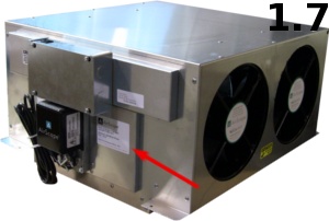
| 1.7WHF | 22.5 | 14.5 | 2.27 | 7 | 22.66 |
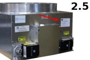
| 2.5, 2.5eWHF | 22.5 | 14.5 | 2.27 | 10 | 15.86 |
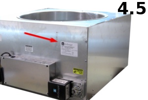
| 4.5WHF | 26.5 | 22.5 | 4.14 | 10 | 28.98 |
Bottom line: There is not much heat loss through a well insulated whole house fan damper door. The question that you SHOULD be asking is: “How well sealed is the whole house fan damper door?”
Most residential windows will have R values of 1 to 3. Another question that we get all the time is : “What is a BTU ?”
BTU stands for British Thermal Unit.
1 BTU is approximately the energy released by burning 1 paper match.
100,000 BTU’s make up one therm – that’s how you purchase natural gas, and right now that costs about $1.50
A gallon of gas has about 114,000 BTU.


